Linear actuators convert fluid pressure or electrical energy into mechanical straight-line motion. When comparing hydraulic, pneumatic, and electric linear actuators, your selection depends on three core engineering constraints: force density, operational speed, and positioning accuracy.
Hydraulic actuators use pressurized oil to move heavy industrial loads with massive force. Pneumatic cylinders rely on compressed air to deliver rapid, low-cost, point-to-point motion. Electric linear actuators combine rotary motors with precision drive screws to deliver programmable acceleration, sub-millimeter positioning accuracy, and quiet energy efficiency.
Quick Take: Matching the Actuator to Your Application
Each actuator type excels within specific mechanical boundaries determined by its underlying power source:
- Hydraulic Actuators: Best for high-load applications requiring pressures up to 3,000+ psi and tens of thousands of pounds of force in rugged industrial environments.
- Pneumatic Actuators: Ideal for rapid, repetitive, point-to-point transfer tasks where factory compressed air is already installed and upfront hardware budgets are tight.
- Electric Actuators: The premier choice for automated machinery requiring multi-stop positioning, variable speed profiles, zero fluid-leak tolerance, and energy efficiency.
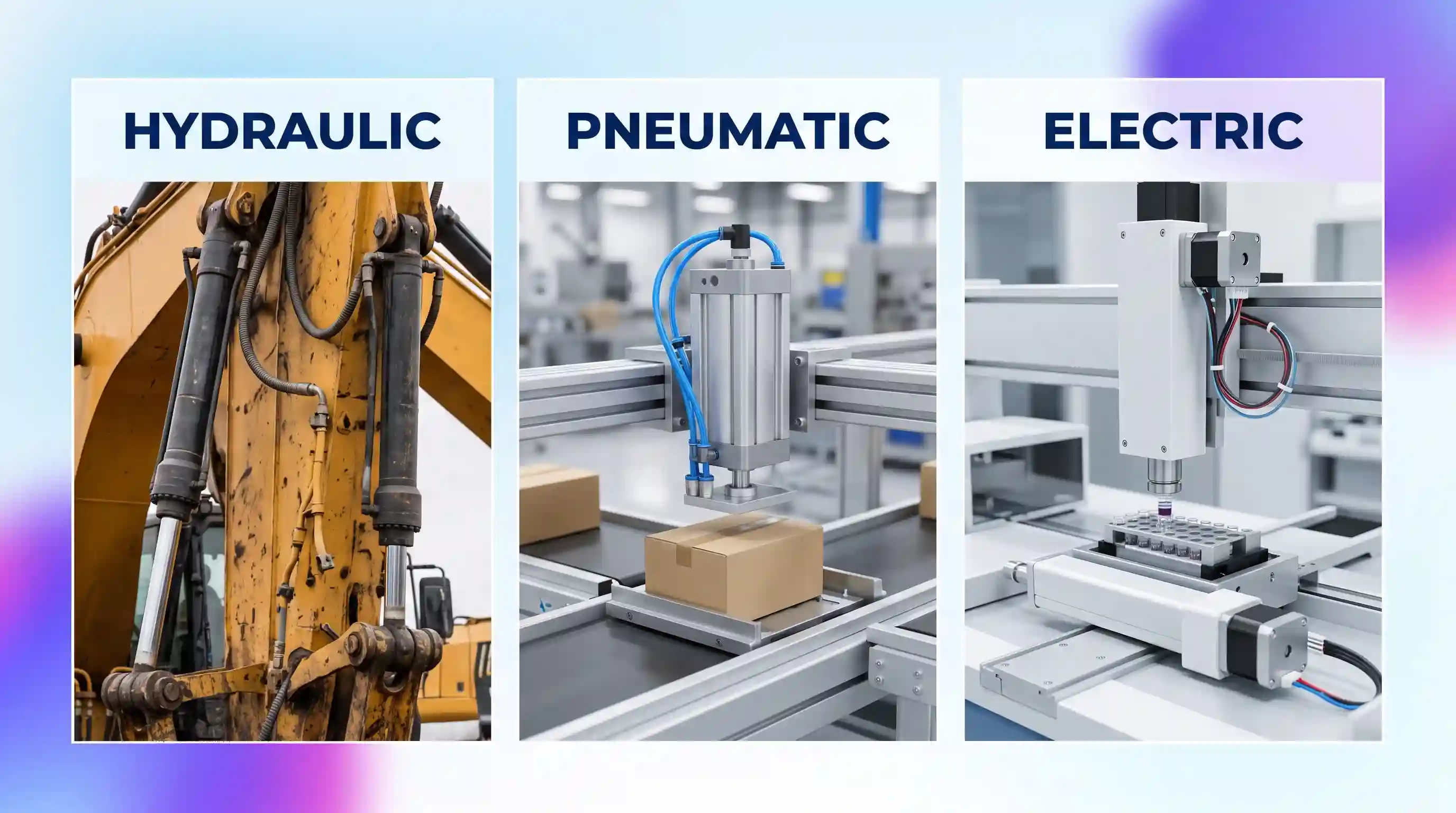
How Linear Actuators Create Straight-Line Motion
A linear actuator creates mechanical push-and-pull movement along a single axis. While standard electric motors spin continuously on an axle, linear actuators convert rotational motion or fluid displacement into linear travel along a defined stroke length. In industrial manufacturing, packaging plants, and robotic cells, designers integrate these actuators into automated motion control systems to position parts, open gates, clamp workpieces, and lift assemblies.
Choosing the wrong drive mechanism can lead to frequent equipment breakdowns, product contamination, or excessive electrical utility bills. To select the right drive, engineers must evaluate how each technology operates, what auxiliary hardware it requires, and where its physical limitations lie.
Hydraulic Linear Actuators: High-Force Fluid Power
A hydraulic actuator operates using high-pressure fluid to generate mechanical force. An external motor-driven pump forces hydraulic oil—typically a mineral-based petroleum or fire-resistant fluid—through rigid steel piping into a sealed cylinder barrel. When the pressurized oil pushes against an internal piston, the piston rod extends outward. Reversing the flow through directional directional control valves pushes the piston backward to retract the rod.
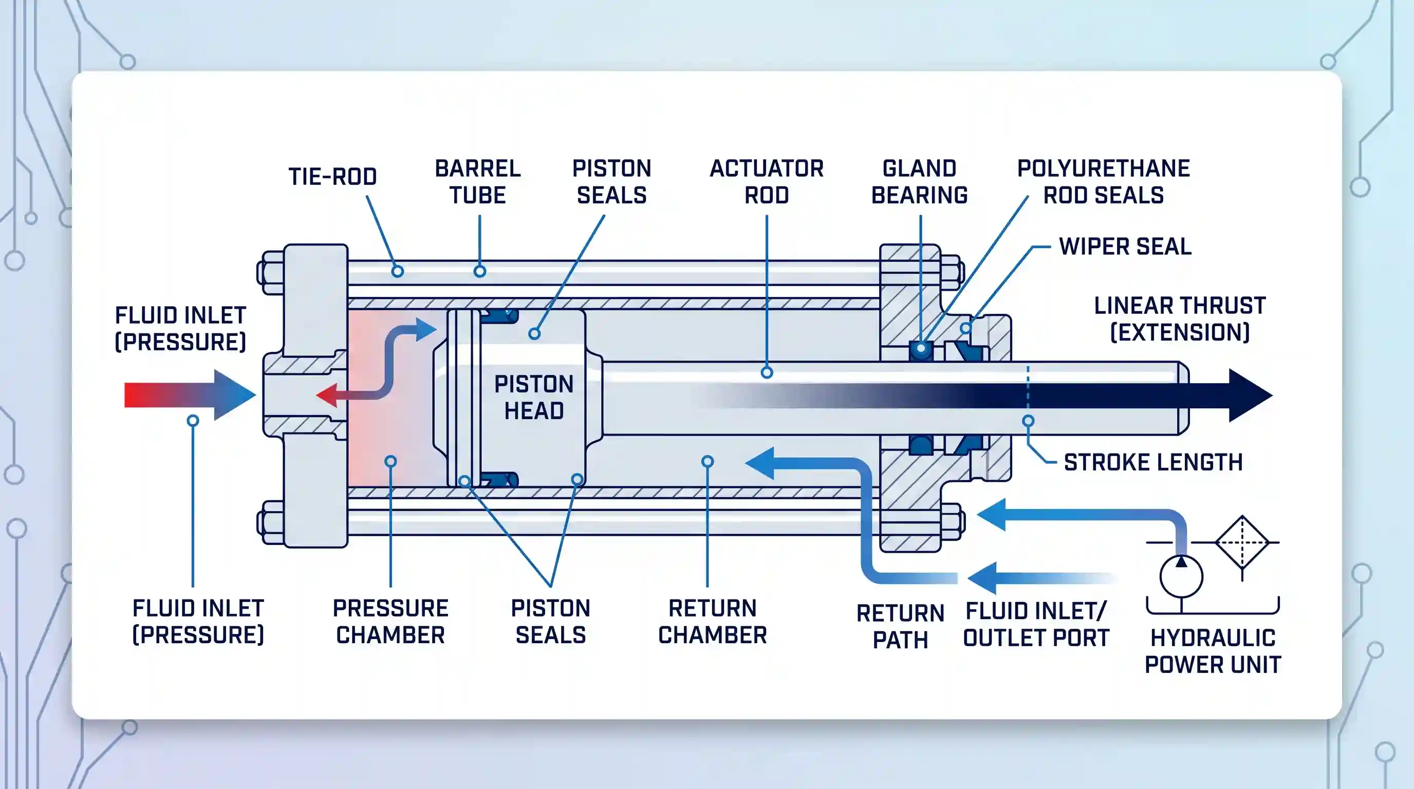
Because oil is an incompressible liquid, hydraulic cylinders provide remarkable mechanical rigidity. Standard industrial hydraulic systems run at internal pressures between 1,500 and 3,000+ psi (100 to 200+ bar). This high pressure allows a compact cylinder to generate thousands of pounds of thrust without hesitation. Furthermore, hydraulic fluid absorbs physical impacts naturally, protecting structural linkages when a machine encounters heavy shock loads or sudden mechanical stalls.
The primary downside of hydraulic power is system complexity. A hydraulic cylinder cannot operate alone; it requires a complete hydraulic power unit (HPU) containing an electric drive motor, fluid pump, oil reservoir, fluid cooler, and filtration bank. Hydraulic lines require regular maintenance to monitor fluid cleanliness, change filters, and check for hose wear. If a fitting fails, leaking hydraulic oil creates serious slipping hazards, environmental contamination issues, and potential fire risks around high-temperature machinery.
Pneumatic Linear Actuators: Rapid Motion via Compressed Air
Most industrial pneumatic cylinders run on shop air to create linear motion. A central air compressor draws in ambient air, compresses it, and routes it through refrigerated dryers and centralized distribution pipes. Before entering the cylinder, the air passes through specialized FRL air preparation units that filter out dirt particles, regulate air pressure, and inject trace lubricants to extend seal life.
Pneumatic cylinders excel in speed and mechanical simplicity. Because compressed air flows rapidly through supply lines with negligible viscous friction, pneumatic pistons can achieve travel speeds exceeding 40 inches per second. Pneumatic cylinders feature few moving parts, making them lightweight, inexpensive to buy, and simple to repair. In addition, because the working fluid is non-flammable ambient air, pneumatic cylinders generate no electrical sparks, making them ideal for spray-painting booths, chemical handling, and grain elevators where explosive dust or vapors are present.
The major drawback of pneumatics is the compressibility of air. Compressed air acts like a mechanical spring inside the cylinder chamber. When external payloads fluctuate during motion, the piston can hesitate, bounce, or jerk unexpectedly. Because of this air bounce, stopping a standard pneumatic cylinder midway through its stroke with tight accuracy is nearly impossible without costly external rod-locking brakes. Consequently, pneumatics remain best suited for simple two-position, end-to-end hard-stop cycling.
Electric Linear Actuators: Programmable Precision and High Efficiency
Electric linear actuators convert rotational motor torque directly into straight-line mechanical motion. The actuator houses an electric motor—such as a brushless DC servo or stepper motor—coupled to a precision threaded screw. As the motor rotates the drive screw, an internal nut travels along the threads, pushing the actuator rod outward or pulling it back inward.
Depending on the required force and duty cycle, manufacturers construct electric actuators with different screw technologies. Low-cost units use sliding Acme lead screws, whereas industrial automation platforms use low-friction recirculating ball screws that achieve mechanical efficiency ratings above 90%. For extreme heavy-duty applications, specialized roller screw electric actuators deliver massive thrust up to 222 kN (50,000 lbf), competing directly with hydraulic cylinders.
In modern industrial facilities, migrating to electric linear systems simplifies machine changeovers because technicians can reprogram stroke lengths, travel velocities, and acceleration ramps in software rather than repositioning physical proximity switches. In contrast, an Actuator linear system delivers superior lifecycle economics by drawing electrical current only during active motion. Equipped with digital position feedback sensors, electric actuators connect directly to factory programmable logic controllers to deliver repeatable sub-millimeter precision across millions of operating cycles.
Head-to-Head Specification Comparison
The comparison table below details the performance characteristics, infrastructure needs, and operational trade-offs for each linear actuator technology:
| Specification Parameter | Hydraulic Actuators | Pneumatic Actuators | Electric Actuators |
|---|---|---|---|
| Working Medium | Pressurized mineral oil or fluid | Filtered, dried shop air | Electric motor drive (DC, Stepper, Servo) |
| Operating Pressure | 1,500 to 3,000+ psi (100–200+ bar) | 80 to 120 psi (5.5–8.3 bar) | Not applicable (mechanical screw transmission) |
| Force Density | Extremely high (tens of thousands of lbf) | Low to moderate (limited by air pressure) | Moderate to high (roller screw options) |
| Stroke Cycle Speed | Moderate (controlled flow rate) | Very high (up to 40+ in/sec) | Adjustable (slow creep to 40+ in/sec) |
| Positioning Precision | Moderate (requires servo valves) | Low (springy air limits mid-stroke hold) | Extremely high (±0.001 in / ±0.025 mm) |
| System Energy Efficiency | Moderate (constant pumping losses) | Low (compressor heat and leak waste) | High (75% to 80%+ direct conversion) |
| Support Infrastructure | Large (HPU pump, reservoir, cooler, hoses) | Medium (compressor, dryer, FRL, rigid pipes) | Compact (cables, drive controller, power supply) |
| Maintenance Burden | High (fluid tests, seal leaks, filter swaps) | Moderate (air line filters, seal wear) | Low (lubricated for life, periodic checks) |
| Environmental Cleanliness | High leak hazard (oil drips and spills) | Clean, but exhausts ambient air and trace oil | Cleanest (zero fluid, cleanroom compatible) |
Mechanical Failure Modes and Operating Limits
Operating an actuator beyond its designed mechanical envelope leads to premature failure. Every mechanical designer should watch out for these common failure modes:
- Side-Load Deflection: Linear actuators are built strictly to push and pull loads along their central axis. Exposing an actuator rod to lateral side forces bends internal drive screws, wears guide bushings, and tears rod seals. When moving loads that shift off-center, always support the payload with external linear guide rails so the actuator only handles axial thrust.
- Duty-Cycle Thermal Throttling: Electric actuators with Acme lead screws have typical duty-cycle ratings between 20% and 50% to prevent frictional heat from softening the drive nut or overheating the motor windings. Operating continuously without cooling periods causes thermal shutdowns. In contrast, hydraulic cylinders handle continuous cycling because recirculating oil carries friction heat away to an external heat exchanger.
- Air Moisture and Piston Seal Degradation: If compressed air systems lack adequate dryers, water vapor condenses inside pneumatic lines. This moisture washes away internal grease, corrodes the aluminum cylinder bore, and hardens rubber piston seals. Once seals degrade, air leaks past the piston head, causing sluggish cycling and loss of holding thrust.
Total Cost of Ownership: Upfront Price vs. Operating Cost
Looking only at the initial purchase price of an actuator can lead to expensive miscalculations over the life of a machine:
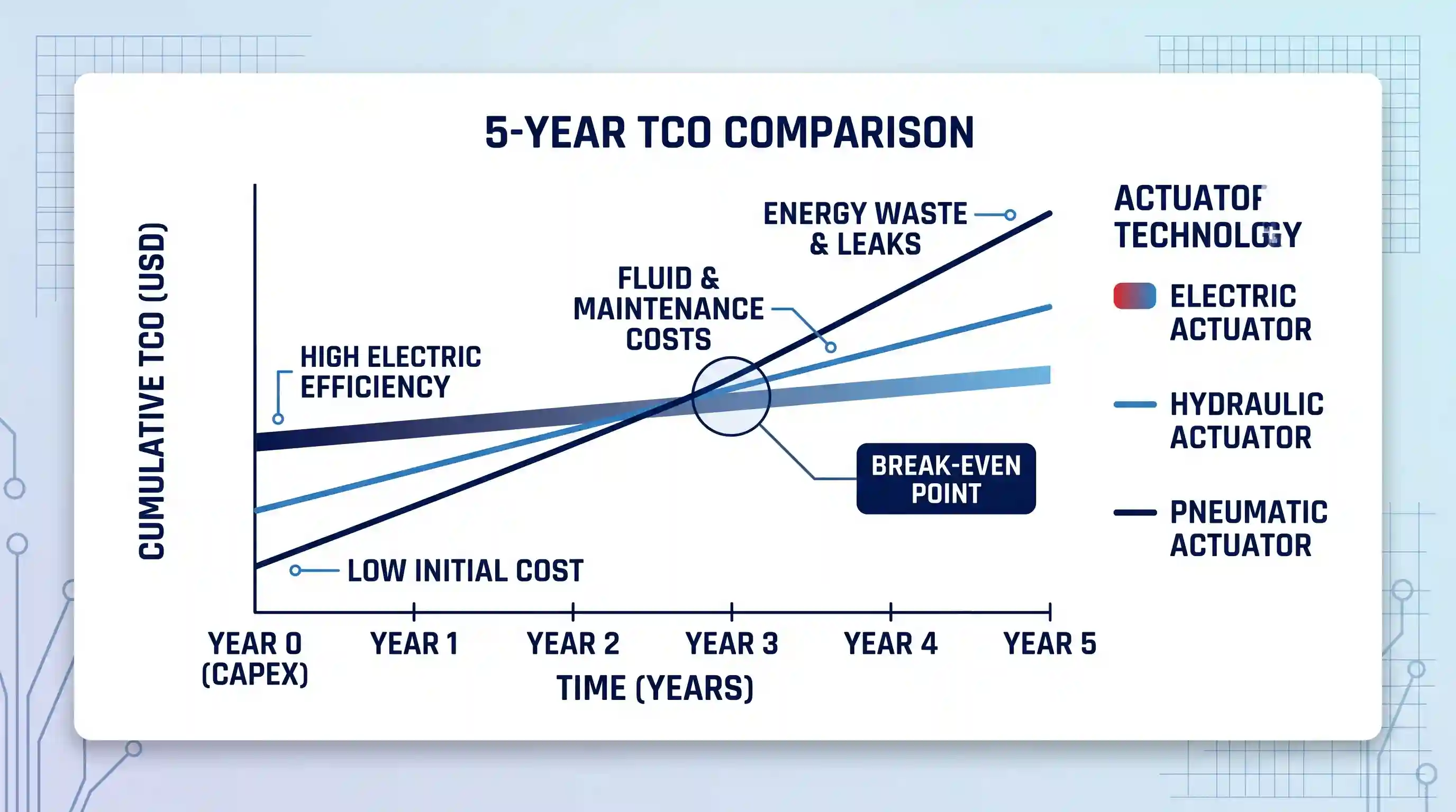
Pneumatic cylinders have the lowest initial purchase price, often costing less than one-third the price of an equivalent electric system. However, technical energy audits confirm that an industrial pneumatic system operates near 20 percent efficiency because massive amounts of electrical energy are lost as heat during air compression. Compounding this loss, plant-wide surveys show that unattended compressed air leaks consume 20 to 30 percent of total compressor capacity. For high-duty manufacturing equipment operating across multiple shifts, the annual electricity bill to power a pneumatic cylinder frequently eclipses the initial hardware cost within months.
Hydraulic systems have moderate energy efficiency and high initial installation costs due to the required pumps, reservoirs, and fluid distribution circuits. Ongoing expenses include replacement hydraulic fluids, hazardous waste disposal, filter cartridges, and labor hours spent cleaning up leaks. However, when an application requires brute lifting capacity, hydraulics remain the most cost-effective solution per pound of delivered force.
Electric linear actuators carry the highest upfront hardware price tag, requiring precision ground screws, servomotors, encoder sensors, and motor drives. However, electric drives draw power only when actively moving, converting 75% to 80%+ of incoming electrical energy directly into mechanical work. On high-speed assembly lines, the substantial energy savings, reduced maintenance downtime, and lack of compressed air infrastructure often pay back the higher purchase cost within one to two years.
Decision Framework: How to Select the Right Actuator
Follow this decision framework to match your machine requirements with the best actuator technology:
- Choose a hydraulic linear actuator if:
- Your payload requires more than 5,000 to 10,000 pounds of linear thrust.
- The mechanism experiences severe physical shock loads or needs rigid load holding without electrical power.
- The machine operates outdoors in mobile construction, agricultural, or mining equipment.
- Choose a pneumatic linear actuator if:
- The application performs simple two-position transfer, pushing, or sorting strokes.
- High travel speed (over 30 inches per second) is required on a tight hardware budget.
- The work environment requires spark-free hardware due to volatile gases or combustible dust.
- Your facility already has a well-maintained, centralized compressed air supply.
- Choose an electric linear actuator if:
- Your process requires multi-stop positioning, sub-millimeter precision, or adjustable speeds.
- You need to gather digital telemetry (position, motor current, velocity) for predictive maintenance.
- The machine operates in a food, pharmaceutical, or cleanroom environment where oil leaks cannot be tolerated.
- Low operating noise and high energy efficiency are core project requirements.
Common Industry Misconceptions
When planning automation projects, beware of these common engineering assumptions:
Misconception: Pneumatics are always the cheapest motion option.
While pneumatic cylinders and solenoid valves have low retail purchase prices, compressed air is the most expensive industrial utility. Energy losses from compressors and pipe leaks make pneumatics far more expensive to run long-term than electric alternatives.
Misconception: Electric actuators cannot replace hydraulic power.
Modern heavy-duty electric actuators equipped with planetary roller screws generate up to 50,000 pounds of force, allowing machine builders to replace messy hydraulic rams on metal-stamping, pressing, and injection-molding machines.
Misconception: Hydraulics are an outdated technology.
While electric actuators continue to replace hydraulic cylinders in clean indoor plants, hydraulic fluid power remains unmatched for power density, shock resistance, and ruggedness on excavators, marine vessels, and heavy forging presses.
Key Takeaways
- Hydraulic actuators provide unmatched force density and shock tolerance for heavy industrial loads, but require large fluid power units and present persistent oil leak risks.
- Pneumatic cylinders deliver high cycle speeds and low initial purchase costs for simple two-point motions, but suffer from spongy position control and low thermodynamic efficiency.
- Electric linear actuators offer superior positioning accuracy, programmable motion parameters, quiet operation, and high energy efficiency.
- Always evaluate the total cost of ownership—including electrical utility bills, auxiliary infrastructure, and routine maintenance labor—rather than focusing solely on upfront hardware costs.
- Protect actuator rods from side-load forces by installing external linear guide rails to support offset mechanical weights.
Frequently Asked Questions
Can a pneumatic cylinder stop accurately at intermediate positions?
Stopping a standard pneumatic cylinder mid-stroke with repeatable accuracy is difficult because compressed air remains naturally elastic. When payload resistance changes, the air pocket compresses and expands, causing the piston to bounce or overshoot the target position. While specialized proportional valves and external rod-locking brakes allow intermediate stopping, they add substantial cost and plumbing complexity. If your application demands repeatable multi-stop positioning, an electric linear actuator provides a much more reliable solution.
What routine maintenance do hydraulic actuators require?
Hydraulic actuators require regular fluid condition sampling to detect metal particles and water contamination, scheduled oil filter element replacements, reservoir fluid top-offs, and routine hose inspections for cracks or wear. Maintenance personnel must also regularly inspect the cylinder rod wiper seals to ensure environmental dirt does not enter the cylinder and score the polished barrel walls.
What happens to an electric actuator if power is suddenly lost?
An electric actuator’s behavior during a power outage depends on its internal drive screw design. Actuators equipped with high-friction Acme lead screws generally self-lock under load, holding their position when power drops. In contrast, actuators built with low-friction ball screws or roller screws can back-drive under heavy external payloads unless the motor assembly includes an integrated spring-applied electromechanical brake.
Are pneumatic actuators safe for hazardous or explosive environments?
Yes. Because pneumatic cylinders rely entirely on mechanical air pressure without electrical coils or motor windings at the actuator body, they are inherently spark-free. This makes them standard choices for explosive environments, paint-spray booths, and chemical facilities where electrical arcs could ignite flammable vapors or combustible dust.

💬 Comments